ESP32 DevKit
Introduction
UART0
Do NOT connect a peripheral to UART0 (GPIO1, GPIO3). UART0 is used by the ESP32's bootloader and by the firmware to print messages.
Input-Only Pins
Pins GPIO 34, 35, 36, and 39 are input-only pins and cannot be used as outputs. If you are not sure what that means, do not use these pins at all.
To use this board please refer to the Device
Profile called nodemcu_esp32.json or
blinkyparts_esp32.json. Both are nicely compatible with the dev board. Open
the JSON file with a text editor and have a look at the specific pin numbers.
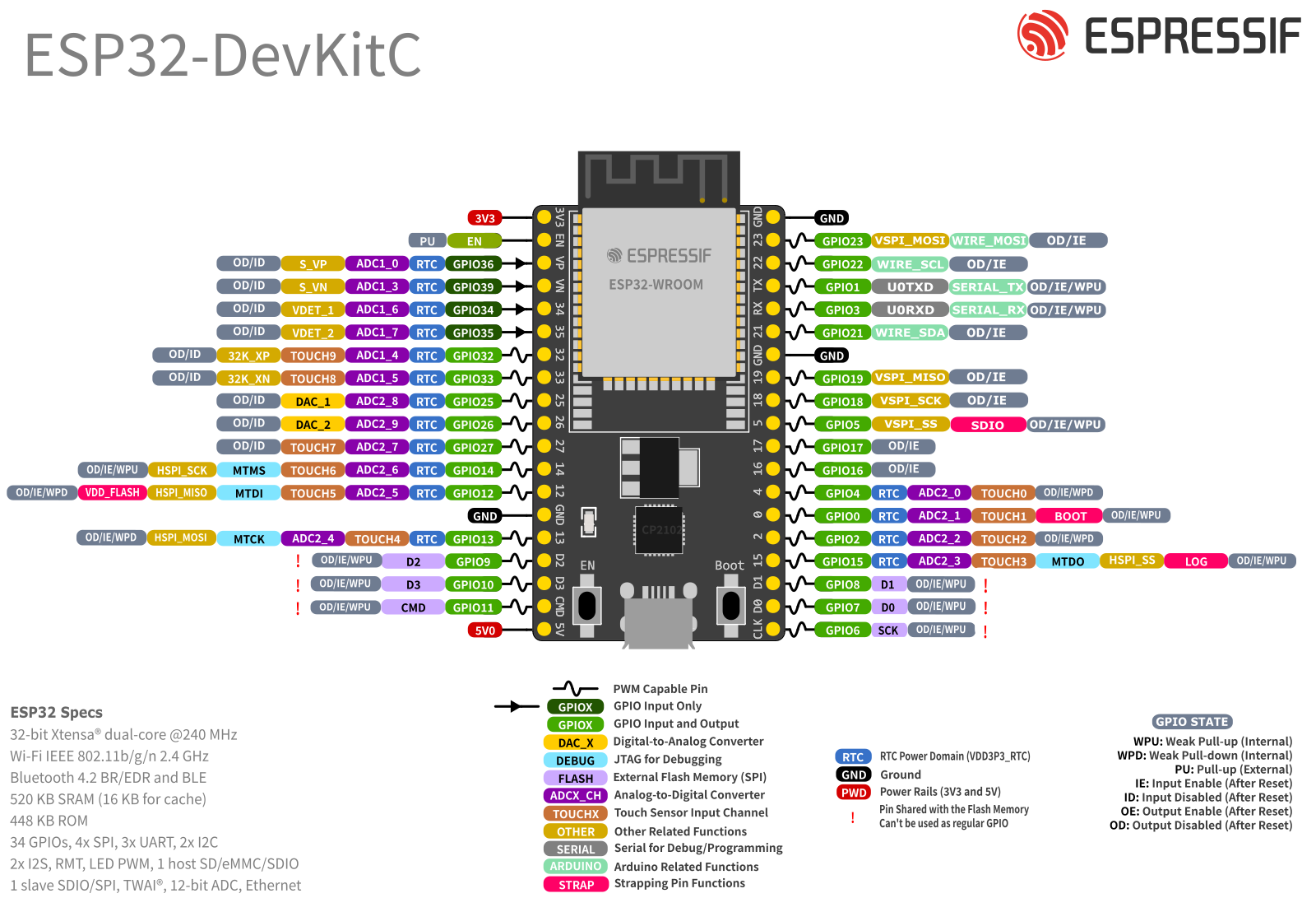
Overview
The following is an overview of the original Espressif ESP32 DevKit board. Many boards offered on well-known larger Chinese or local web stores are usually merely compatible imitations.
Flash Memory
Flash Memory
Get a version with at least 8 MB of flash memory to be able to use OTA updates.
Versions of this board with 8 MB or more of flash memory are available, but harder to find. When searching for such a board by keywords, mostly ESP32-S3 boards come up.
Note that Espressif offers the following ESP32-DevKitC variants:
| Board Name | Module | Flash | PSRAM | Antenna |
|---|---|---|---|---|
| ESP32-DevKitC-32E | ESP32-WROOM-32E | 4 MB | - | PCB Trace |
| ESP32-DevKitC-32UE | ESP32-WROOM-32UE | 4 MB | - | external |
| ESP32-DevKitC-VE | ESP32-WROVER-E | 8 MB | 8 MB | PCB Trace |
| ESP32-DevKitC-VIE | ESP32-WROVER-IE | 8 MB | 8 MB | external |
The ESP32-DevKitC-VIE also has a PCB trace antenna, which can be used instead of the external PCB connector by re-soldering the respective resistor close to the antenna connector into the respective position. This requires soldering experience due to the small size of the resistor.
Sources for genuine ESP32-DevKitC-VIE:
At the time of writing, the distributors listed above also offer the ESP32-DevKitC-VE board.
Use the respective full board name to find these boards in other online stores.
Schematic
Example
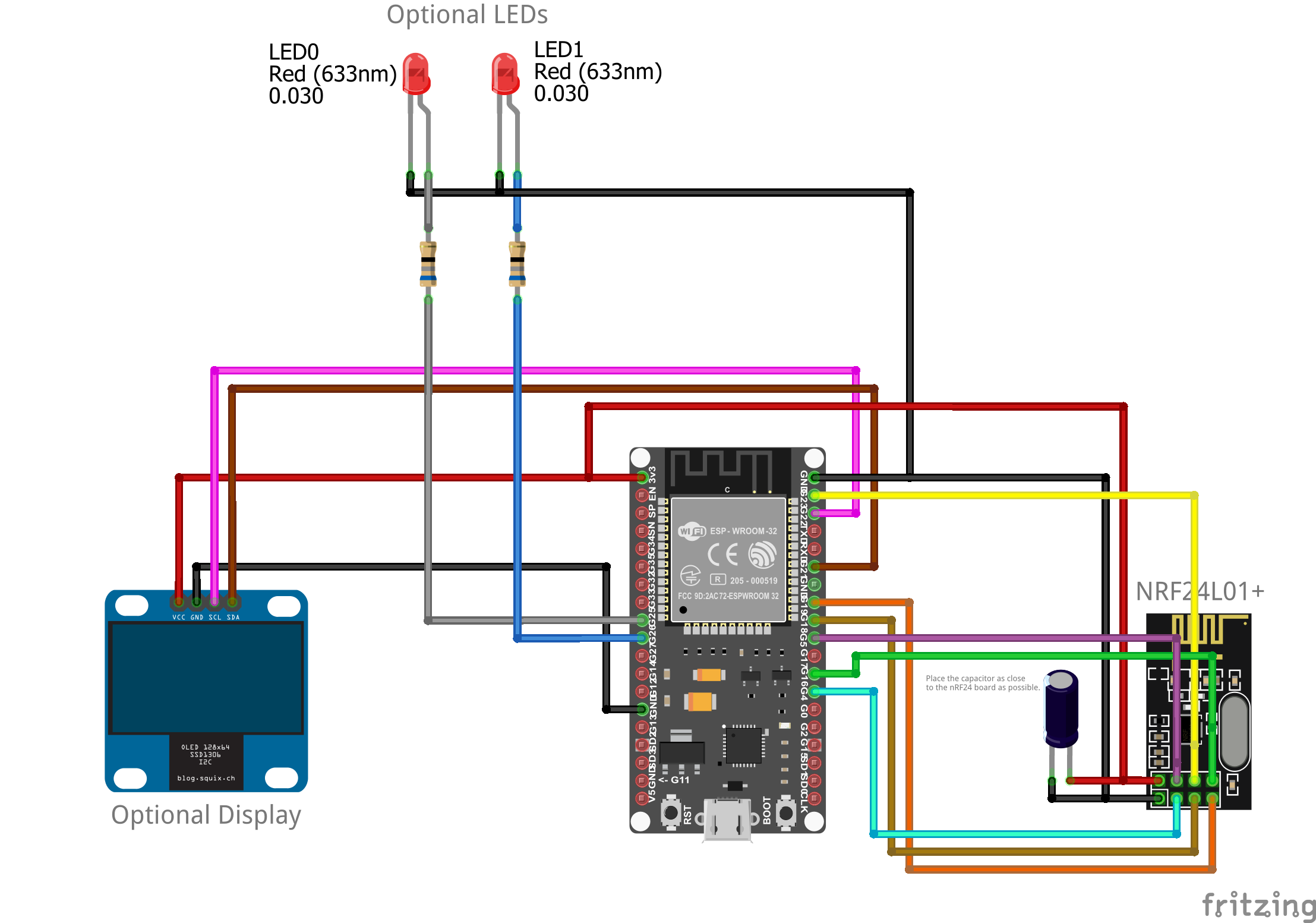
This is merely an example. You may need a different RF module to support your inverter. The display and LEDs are optional. You may wire the components to other GPIOs, if you upload a matching Device Profile.

Symbolic View
Example
This is merely an example. You may need a different RF module to support your inverter. The display and LEDs are optional. You may wire the components to other GPIOs, if you upload a matching Device Profile.